Description
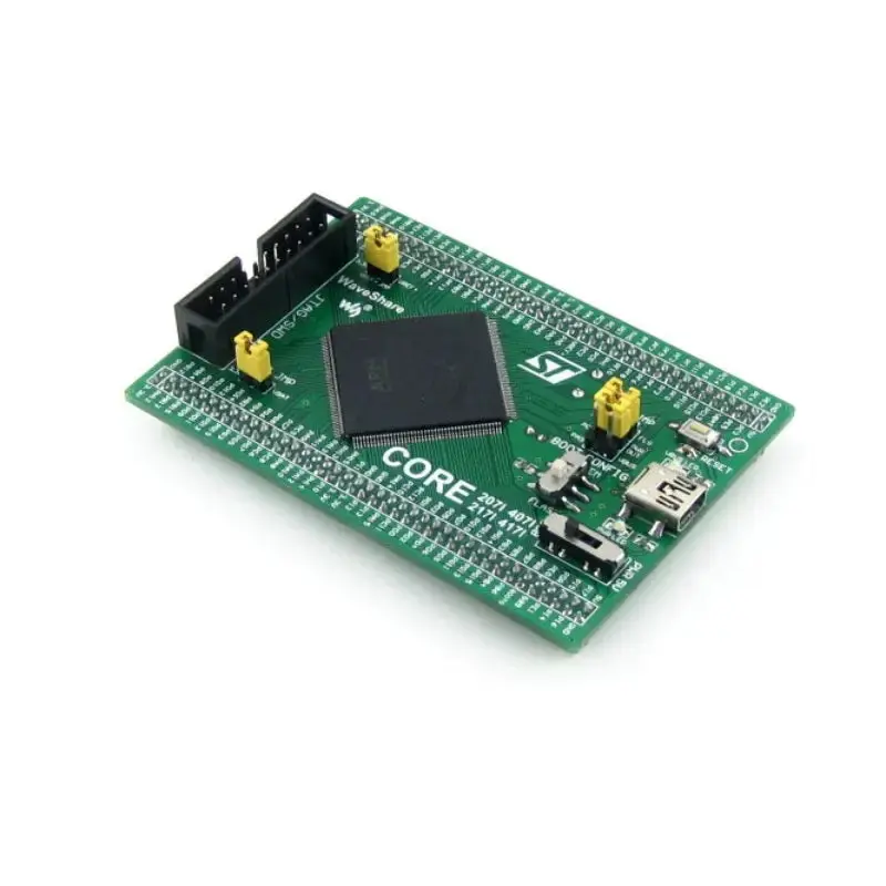
- Waveshare Core407I STM32F4 Core Board
- Integrates STM32F407IGT6 MCU for high performance
- Supports multiple communication interfaces
- Features USB communication as device and host
- Includes debugging and programming interfaces
- Offers customizable I/O port access with expansion connectors
The Waveshare Core407I STM32F4 Core Board is a compact development platform featuring the STM32F407IGT6 microcontroller, designed for initiating application development within the STM32F family. This board integrates essential components such as a USB communication interface, JTAG/SWD programming and debugging interface, clock circuit, and USB power management. It also includes a boot mode selection feature, making it a comprehensive, ready-to-run system.
The board is equipped with pin headers on the backside, allowing it to be easily integrated into application boards, serving as the MCU core circuit. All input/output ports are accessible via these pin headers, which are designed with a 2.0mm pitch to minimize PCB size. The STM32F407IGT6 microcontroller offers high performance with a Cortex-M4 32-bit RISC core, operating at a frequency of 168MHz. It supports a wide range of communication interfaces, including SPI, USART, UART, I2S, I2C, FSMC, SDIO, CAN, USB 2.0, and Ethernet MAC.
Additional features include AD and DA converters, a power supply switch, a boot mode switch, power indicators, and a reset button. The board also supports USB communication as both a device and a host, with the capability to connect to USB devices via an OTG cable. Expansion connectors provide access to all I/O ports, VCC, and GND, facilitating further development and customization.
View moreWhat’s Included
- 1x Waveshare Core407I STM32F4 Core Board
- 1x USB Type A to Mini-B Cable
Dimensions
Links
Website
Core407I, STM32F4 Core Board – Core407I Wiki
Specifications
- STM32F407IGT6: High-performance STM32 microcontroller unit
- Core: Cortex-M4 32-bit RISC architecture
- Feature: Complete set of single-cycle DSP instructions
- Operating Frequency: 168 MHz, 210 DMIPS/1.25 DMIPS/MHz
- Operating Voltage: 1.8V-3.6V
- Package: LQFP176
- Memory: 1024 kB Flash, 192+4 kB SRAM
- Communication Interfaces: 3 x SPI, 4 x USART, 2 x UART, 2 x I2S, 3 x I2C, 1 x FSMC, 1 x SDIO, 2 x CAN
- USB 2.0 high-speed/full-speed device/host/OTG controller with dedicated DMA, ULPI, and on-chip full-speed PHY
- 10/100 Ethernet MAC
- 8 to 14-bit parallel camera interface
- AD & DA Converters: 3 x AD (12-bit, 1s, shares 24 channels); 2 x DA (12-bit)
- Debugging/Programming: Supports JTAG/SWD (serial wire debug) interfaces, supports IAP
- AMS1117-3 (on bottom side), 3.3V voltage regulator
- MIC2075 (on bottom side), onboard USB power management device
- Power supply switch, powered from 5Vin or USB connection
- Boot mode switch, for configuring BOOT0 pin
- Power indicator
- VBUS LED
- Reset button
- 8M crystal oscillator (on bottom side)
- 32.768K crystal (on bottom side), for internal RTC with calibration
- JTAG/SWD interface: For debugging/programming
- USB interface: As DEVICE, used for establishing USB communication between PC and the STM32 development board; As HOST, connecting to USB devices such as USB flash drive through a USB OTG cable
- MCU pins expander, VCC, GND, and all the I/O ports are accessible on expansion connectors for further expansion
- 5Vin pinheader, 5V power supply is required when using USB HOST/OTG
- USB HOST/OTG jumper: Short the jumper when using USB HOST/OTG; Open the jumper to disconnect from I/O port
- VBAT selection jumper: Short the jumper to use system power supply; Open the jumper to connect the VBAT to external power, such as a battery
- VREF selection jumper: Short the jumper to connect VREF+ to VCC; Open the jumper to connect VREF+ to another custom pin via jumper wire