Description
- Waveshare CoreH743I STM32H743IIT6 MCU Core Board
- Features high-performance STM32H743IIT6 microcontroller
- Supports extensive connectivity with all I/O ports accessible
- Includes onboard 64M Bit SDRAM and JTAG/SWD interfaces
- Offers USB device/host modes and onboard power management
- Enables easy integration with 2.0mm header pitch
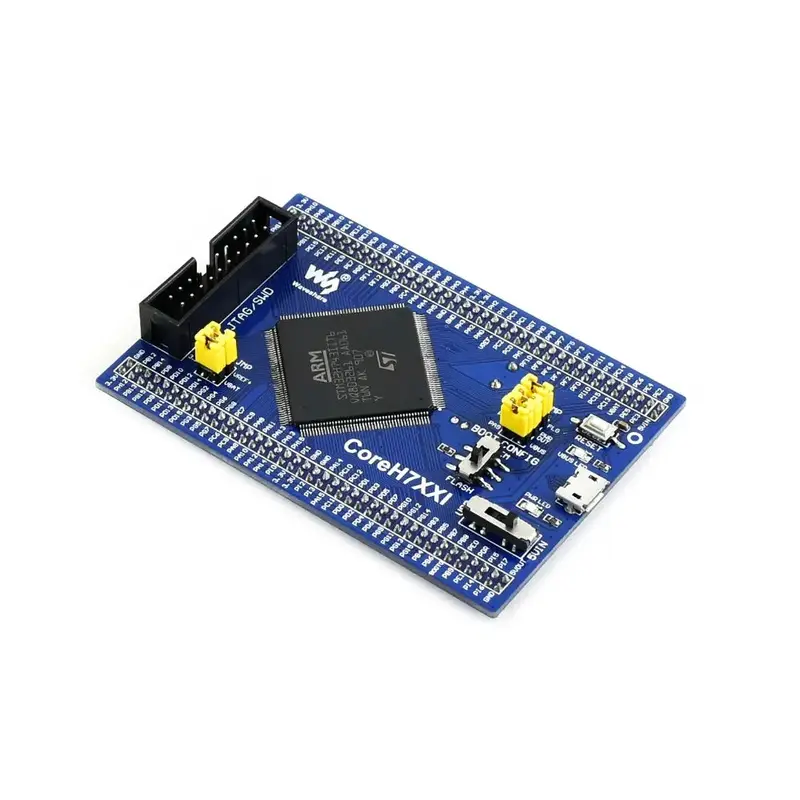
The Waveshare CoreH743I STM32H743IIT6 MCU Core Board is a sophisticated microcontroller unit designed for advanced application development within the STM32H family. It features a high-performance STM32H743IIT6 microcontroller, which includes a Cortex-M7 32-bit RISC core with a double-precision floating-point unit and Chrom-ART graphic accelerator. This board is equipped with a minimal ready-to-run system, integrating essential components such as a clock circuit and USB power management.
The board supports extensive connectivity options, with all I/O ports accessible via pin headers, facilitating further expansion. It includes onboard 64M Bit SDRAM and supports JTAG/SWD programming and debugging interfaces. The board’s design allows it to be easily integrated into application boards with a 2.0mm header pitch.
Additional features include a USB connector that supports both device and host modes, a power supply switch, and various indicators such as VBUS and power LEDs. The board also provides options for boot mode selection and includes a reset button for convenience. It is powered either through a 5V input or a USB connection, with provisions for external power sources.
Note: CoreH743I provides a JTAG/SWD debugging interface but does not integrate any debugging function; a separate debugger is required.
View moreWhat’s Included
- 1x Waveshare CoreH743I STM32H743IIT6 MCU Core Board
- 1x USB Type A plug to Micro B plug cable
Dimensions
Links
Website
CoreH743I, STM32 STM32H743IIT6 MCU core board – CoreH743I Wiki
Specifications
- STM32H743IIT6: High-performance STM32 MCU
- Core: Cortex-M7 32-bit RISC with double-precision FPU and Chrom-ART graphic accelerator
- Feature: Single-cycle DSP instructions
- Operating Frequency: 480MHz, 1027 DMIPS / 2.14 DMIPS/MHz
- Operating Voltage: 1.62V-3.6V
- Package: LQFP176
- Memories: 2MB Flash, 1MB RAM (864KB User + 192KB TCM + 4KB Backup)
- MCU Communication Interfaces: 6 x SPI, 4 x USART, 4 x UART, 1 x LPUART, 3 x I2S, 4 x I2C, 2 x FDCAN, 1 x QUAD-SPI, 1 x DCMI, 4 x SAI, 1 x FMC, 2 x SDMMC, 10 x TIM, 5 x LPTIM, 1 x LTDC, 1 x SPDIFRX, 1 x HDMI-CEC, 1 x SWPMI, 2 x COMP, 2 x OPAMP, 1 x HRTIM, 1 x RNG, 1 x DM2D, 1 x MDIO, 1 x SysTick
- 1 x USB 2.0 OTG FS
- 1 x USB 2.0 OTG HS (supports external HS PHY through ULPI)
- 1 x 10/100 Ethernet MAC
- AD & DA Converters: 3 x AD (16-bit); 2 x DA (12-bit)
- Debugging/Programming: Supports JTAG/SWD interfaces, supports IAP
- IC42S16400J / IS42S16400J: SDRAM 1 Meg Bits x 16 Bits x 4 Banks (64-MBIT)
- STMPS2151STR: Onboard USB power management device
- AMS1117-3.3V Voltage Regulator
- 8M Crystal
- 32.768K Crystal for internal RTC with calibration
- Reset Button
- VBUS LED: USB port indicator
- PWR LED: Power indicator
- Power Supply Switch, powered from 5Vin or USB connection
- Boot Mode Selection for configuring BOOT0 pin
- JTAG/SWD Interface for debugging/programming
- USB Connector supports Device and/or Host
- MCU Pins Expander: VCC, GND, and all I/O pins accessible on expansion connectors
- POWER Jumper
- VBAT: Short the jumper to use system power supply, open it to connect external power
- VREF: Short the jumper to connect VREF+ to VCC, open it to connect VREF+ to other custom pin
- OTG Jumper: Short the jumper when using USB OTG/HOST, open the jumper to disconnect from related I/O port