$23.51
$29.39
50% OFF! Hot items selling fast—Grab them before they're gone!
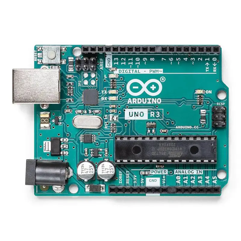
The Arduino Uno is a microcontroller board based on the ATmega328 microchip. It has 14 digital input/output pins (of which 6 can be used as PWM outputs), 6 analog inputs, a 16 MHz crystal oscillator, a USB connection, a power jack, an ICSP header, and a reset button. It contains everything needed to support the microcontroller; simply connect it to a computer with a 1.5m USB Cable Type A to Bor power it with a Wall Adapter Power Supply – 9VDC 650mA or DFRobot 7.4V Lipo 2500mAh Battery (Arduino Power Jack) to get started.
The Arduino Uno differs from all preceding boards in that it does not use the FTDI USB-to-serial driver chip. Instead, it features the Atmega16U2 programmed as a USB-to-serial converter. “Uno” means one in Italian and is named to mark the upcoming release of Arduino 1.0. The Uno and version 1.0 will be the reference versions of Arduino, moving forward. The Uno is the latest in a series of USB Arduino boards, and the reference model for the Arduino platform.
The Arduino Uno can be powered via the USB connection or with an external power supply. The power source is selected automatically. External (non-USB) power can come either from an AC-to-DC adapter (wall-wart) or battery. The adapter can be connected by plugging a 2.1 mm center-positive plug into the board’s power jack. Leads from a battery can be inserted in the Gnd and Vin pin headers of the POWER connector. The board can operate on an external supply of 6 to 20 volts.
The Arduino Uno can be programmed with the Arduino software. Select “Arduino Uno from the Tools > Board menu (according to the microcontroller on your board). For details, see the reference and tutorials. The ATmega328 on the Arduino Uno comes preburned with a bootloader that allows you to upload new code to it without the use of an external hardware programmer.
Power
The Arduino Uno can be powered via the USB connection or with an external power supply. The power source is selected automatically.
External (non-USB) power can come either from an AC-to-DC adapter (wall-wart) or battery. The adapter can be connected by plugging a 2.1 mm center-positive plug into the board’s power jack. Leads from a battery can be inserted in the Gnd and Vin pin headers of the POWER connector.
The board can operate on an external supply of 6 to 20 volts. If supplied with less than 7V, however, the 5V pin may supply less than five volts and the board may be unstable. If using more than 12 V, the voltage regulator may overheat and damage the board. The recommended range is 7 to 12 volts.
The power pins are as follows:
Memory
The ATmega328 has 32 KB (with 0.5 KB used for the bootloader). It also has 2 KB of SRAM and 1 KB of EEPROM (which can be read and written with the EEPROM library).
View moreWhat’s Included
Dimensions
The USB connector and power jack extend beyond these dimensions.
Four screw holes allow the board to be attached to a surface or case.
Note that the distance between digital pins 7 and 8 is 160 mil (0.16″), not an even multiple of the 100 mil spacing of the other pins.
Links
PDF Files
ZIP File
Website
Servo Article
Making Robots With The Arduino, Part 1, by Gordon McComb, Servo Magazine November 2010
Specifications